1. Intelligent power network
The electricity for personal use is generated through the use ofPhotovoltaic (PV)and oneCombined heat and power plant (CHP)provided. To date, one has been expanded40 kW PV systemon the roof of the boiler house. A later PV expansion and thus the use of additional roofs of commercial buildings is planned. In the BHKW is produced by the gasification of wood in addition to heat20 kW electrical energygenerated. Two different battery systems are to be used to temporarily store this energy. OneAC coupled lithium ion batteryensures a high current carrying capacity and the smoothing of current peaks. The capacity (memory size) is with this40kWh. In addition, oneVanadium redox flow batteryplanned. This holds250kWh, is intended to serve as long-term storage and enables the absorption of large amounts of electricity when the CHP is in operation or during long periods of sunshine. Smart meters are used for the intelligent management of electricity volumes. A smart meter has the advantage over a conventional electricity meter that it can pass on its current readings digitally. Using these values, the consumers that can be controlled in the system (sauna, e-charging stations, heat pumps) can be adapted to the current generation output. In the ideal case, this means that you can cover your own electricity needs completely yourself, so that energy only rarely has to be drawn from the power grid.
2. Local heating network controlled by energy quantities
In the farm's local heating network, aWood chip heating (HK), aCombined heat and power plant (CHP)and multiple heat pumps for providing heat. Heat pumps can use thermal energy from their environment (air, water, earth). The advantage of this is that energy can also be extracted from low-temperature systems. At the Klarerhof, three heat pumps are used in the boiler house and one heat pump in the dairy cow barn, which has a total output of3x 16 kW and 1x 6.5 kWcan achieve. More detailed descriptions can be found under the sub-projects".
TheCHPdelivers in parallel during operation60 kW heat and 20 kW electricity, which is why it should only be used when both forms of energy are required. If the electricity storage is already full, the heat is preferably supplied by the wood chip heating system. This has a base load of40kW. To store and distribute the heat were a centralBuffer tank with 26 m³ (26000 L) capacityin the heating house as well as decentralizedBuffer storage (2x 2000L and 1x 1000L)installed at the consumption points. The central buffer tank is charged directly by the heat generators (HK, CHP, heat pumps). An intelligent controller ensures that the buffer is loaded in advance as required. Current weather data and recorded user behavior provide the necessary information.
The subsequent discharging or consumption of the stored heat then takes place through the drying system (if in operation) and the farm's internal local heating network, which at the same time supplies the decentralized buffer storage with heat energy. Intelligent control is also used with regard to the decentralized buffer storage, so that controllable heat consumers such as radiators or pool heating are only supplied when required. While conventional heating systems only measure the average temperature and heat according to this, at the Klarerhof several temperature sensors for each buffer storage tank and numerous measuring devices (heat quantity meters) ensure a precise overview of the energy quantities contained. The supply is therefore energy-quantity-controlled instead of temperature-controlled, is much more precise and ensures a minimum of losses. In addition, this type of system offers excellent monitorability.
An additional special feature is the heat recovery in the local heating pipes. Warm residual water in the pipe system is not cooled down by the environment as is usually the case, so that the heat it contains is lost. Instead, the residual heat is used for the pool or the dryer or fed back to the central buffer as required. In general, the return from the pool is used when the return temperature is greater than 30 °C. When charging the decentralized buffers, the charging processes of the various buffers are combined and charged in such a way that the return temperature is as low as possible. This increases the quotient of transported heat to heat loss from the pipes. When the charging process is complete, the remaining warm water in the flow line is returned to the central buffer via the return line via a short circuit. Separate supply and return lines were also used in the local heating network for better insulation.
3. Fiber optic based IT infrastructure
A fibre-optic network infrastructure was set up between all relevant buildings and facilities at the Klarerhof. Internet speed ismaximum up to 1 GBit/s,while intra-yard a communication speedup to 10 Gbpscan be achieved. Additionally, about thatComprehensive WiFi (Standard 2022: dual-band WiFi 6)Processes can be controlled and intervened everywhere at court, for example by smartphone. This means that different generators and consumers (e.g. outdoor lighting, sauna, pool, drying system) can be switched on or off in the energy network as required.Digital security is guaranteed by a security gateway from Unify.
4. Agricultural drying plant
TheDrying plant at Klarerhofis characterized by its controllability and adaptabilityvarious drying goodsaown development projectand provides in its functioningan innovation of the company Maustronik GmbHConventional drying systems run through a fixed drying program In contrast to this, in the drying system at Klarerhof, humidity and temperature values as well as the volume flow are recorded via installed measuring sensors before and after the material to be dried flows through andmeasured the heat and electrical energy used. The required volume flow and the corresponding temperature can be constantly adapted to the respective drying material via the values obtained. The aim of the regulation is therefore to maximize the transport of water from the material to be dried in relation to the amount of energy used (electricity and heat).A kind of fuzzy controltries to steadily increase this quotient.
In summary, this system offers three decisive advantages over conventional dryers. On the one hand, the energy consumption can be reduced to a minimum due to the controllability, on the other hand, parameter measurements ensure that the desired degree of drying is measurably achieved. In addition, the intelligent control enables freely programmable drying processes, so that each drying process can be adapted to the respective drying material:
-
The controller independently changes the parameters volume flow and temperature so that the drying target is achieved with a minimum of energy consumption. This "learning adaptation" occurs as a reaction to the respective drying status of the hay bales.
-
The drying of wood chips can be optimized by using only residual energy (heat and electricity) from the farm's internal energy network with a flexible time of completion.
-
The same principle applies here as with wood chips, with the difference that drying takes place in the separate drying chamber for hay and timber.
-
In the case of timber, the drying speed is specifically regulated in order to avoid drying cracks. With two additional fans between the exhaust and supply air, the moist exhaust air can be dosed mixed back into the dry air in order to slow down the drying process in a targeted manner. This is necessary if, on sunny days, the incoming air is already too dry for the timber to be dried without being heated. In addition, a probe is attached to the wood with a data connection to the control system in order to record the degree of moisture in the timber.
Working in the interest of ecology means avoiding (energy) losses as far as possible and thus increasing the efficiency of systems. A supply air system was therefore developed for the drying plant that uses as much residual heat as possible from the surrounding plants. As a result, waste heat is used sensibly instead of being lost and the necessary heating energy is saved. The dryer therefore does not draw its supply air directly from the (cool) outside air, but from the heated air cushion below the same building roof. This is where the waste heat from the various heating systems is collected, as well as targeted heat build-up from sunlit facade surfaces. Particular attention is also paid to the heated air cushion below photovoltaic systems. When the sun's rays hit a PV system, only a fraction of the sun's energy can be converted into electricity. The loss is reflected in the heating of the panels and the air below the system. This thermal energy is even 3 to 4 times as high as the usable electrical energy of the PV system itself. The Klarerhof has taken advantage of this fact. The heated air below the PV system is extracted via the gable and also serves as a heat supplier for the drying system.
Furthermore, the (warm) exhaust air is reused in two stages after flowing through the drying material. In the first stage, the exhaust air is routed through a cross heat exchanger and in this way cools down to approx. +2 °C above the temperature of the fresh air. However, this only brings a benefit if the fresh air had to be heated before use in order to have the required low relative humidity for the drying material. Since the supply air, as mentioned above, is drawn from the air cushion that has already been heated, it can in some operating cases be dry enough without being heated. In this case, the use of the cross heat exchanger offers no advantage, since the incoming supply air already has higher temperatures than the exhaust air.
For this reason, in a second stage, the exhaust air (= exhaust air after the cross heat exchanger) is passed through a heat exchanger again, which is cooled with the cold brine from the heat pumps. The residual heat from the exhaust air can thus be stored in the central buffer via the heat pumps and used for heating water. The following sample calculation illustrates the advantage of this system:The heat pumps can produce 48 kW of heat from exhaust air at 20 °C. The exhaust air is cooled down to 11 °C. Depending on the heating water temperature required for the various purposes (heating, hot water, dryer, pool),48 kW heat between 10.8 kW and 15 kW electricityspent on the heat pumps. The heat output and thus also thePower output is from 30% to 100%adjustable for all heat pumps. Since three heat pumps are used in a cascade connection, the power requirement can bebetween approx. 1 kW and 15 kWcan be continuously adjusted to the available self-power.
5. "Heizhaus" project: Use of waste heat to increase the efficiency of heat pumps
In the boiler room of the Klarerhofthree heat pumpsinstalled to provide heat. Deliver thesean output of 16 kW eachand are connected in a cascade for control purposes. They therefore work in the same way as onelarge heat pump with 48 kWperformance, but offer the advantage of better controllability. This advantage pays off above all in winter and in the cool months, so that the additional costs compared to a single, large system are profitable over time. Nowadays, a heat pump makes financial sense, especially when using your own electricity, since the sale of electrical energy hardly brings in any more profit due to the falling feed-in tariff. Heat pumps also speak for themselves from an ecological point of view: the storage of energy in the form of heat (buffer storage) is much easier compared to expensive electricity storage, both in terms of capacity and construction as well as in terms of costs.
Heat pumps have the great advantage that they can use the heat from their immediate surroundings. Depending on the design, they can extract thermal energy from the ambient air, the water or the ground with only a small amount of self-consumption of electricity and make it usable through internal processes. A so-called refrigerant circulates inside the heat pump. This has a very low boiling point, so that it already undergoes the phase transition from liquid to gas at low temperatures. If the heat pump now absorbs external thermal energy, the integrated refrigerant evaporates. The resulting gas is then compressed with the help of electrical energy (= heat pump power consumption) and heats up in the process. The now hot refrigerant gas has about 3 to 8 times more thermal energy than the electrical energy used and can be used, for example, to heat heating water (see Diagram 1). This number factor, also work number orCOP (Coefficient of Performance)called, describes the amount of benefit compared to the energy consumption and illustrates the high potential of heat pumps. Even ambient temperatures of -9 °C can be used to generate heat with the help of heat pumps. However, it should be noted that the heating output and the COP drop significantly at very low temperatures. At the Klarerhof, heat pumps therefore use the waste heat from various systems, which means that COP values greater than 4 can be expected.
Diagram: Simplified scheme of a heat pump
The heat pumps used at the court work with the help of brine, i.e. an optimized liquid for heat absorption and release, which circulates between the "heating place" and the location of the heat pumps. This heat location simply corresponds to the usable environment from which the heat pumps draw their energy as mentioned above. In this project, the environment was chosen in such a way that the waste heat from other systems and facilities can be used sensibly at the same time. In concrete terms, the waste heat from four different sources is collected under the insulated roof of the boiler house (= place of heat):
-
Combined heat and power plant and wood chip heating in the same building
-
Façade warmth of the boiler house: Controllable ventilation flaps are mounted on the east and west sides, which on sunny days can suck off the accumulated heat of the outer walls.
-
Drying system in the same building: Use of the residual heat from the exhaust air of the dryer as a second stage after heat recovery via the integrated cross heat exchanger.
-
PV thermal: If the drying system is not in operation, the heated and extracted air below the photovoltaic system is used as a heat supplier. The amount of energy in the heated air is even 3 to 4 times as high as the usable electrical energy of the PV system itself. In addition, the parallel cooling of the PV system increases its own energy efficiency, since a PV panel works best in a cool environment.
The waste heat from all these systems is therefore collected in one place and is available as a heat supplier. If the drying system is not in operation(see project "Agricultural Drying Plant"), the heat pumps fall back on this warm air cushion. This means that waste heat can be used sensibly and the efficiency of the heat pumps can be significantly increased.

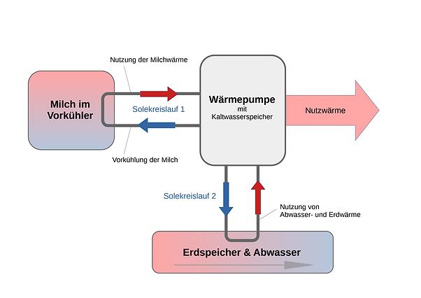
6. "Dairy cowshed" project: Cooling and use of waste heat in one system
In theKlarerhof dairy cow barnseveral advantages are combined by using a heat pump. The cooling process of the milk, both before it enters the tank and in the milk tank itself, is significantly improved. Thermal energy from the milk, the soil and the waste heat from the sewer are used energetically and these heat sources also improve the efficiency of the heat pump itself. In the energy balance, heat losses can be avoided and electricity consumption reduced. In addition, the quality of the milk cooling and thus the hygiene conditions are increased.
-
Optimized use of milk heat:In previous systems, heat was obtained from the milk by cooling it in the milk tank. The chiller, which cools the milk tank, transfers the thermal energy of the milk to a hot water boiler via a heat exchanger. However, this has the disadvantage that the return temperature and thus the temperature of the refrigerant in the compressor increases as a result of the heating of the boiler water. As a result, the quality of the cooling and the efficiency of the chiller decrease steadily. In contrast, with the help of the heat pump, the refrigerant temperature can be regulated in a targeted manner and an energetically optimized cooling process in the tank can be guaranteed. The utilization of the heat from the milk is therefore improved.
-
Increased efficiency of the heat pump:The heat pump at the dairy barn site achieves increased COP values. TheCoefficient of Performance (COP), or work number, describes the benefit of a heat pump (= amount of thermal energy) compared to the necessary electrical energy requirement. By using the waste heat from the milk, the COP can be significantly increased, which means that the required electricity requirement is significantly reduced compared to previous systems.
-
Improved milk pre-cooling: By using the heat pump, the milk is pre-cooled much better before it reaches the milk tank. This is of particular advantage for milking systems with robotic milking. In such systems, only relatively small amounts of milk get into the tank for each milking process, so that the milk cannot be optimally cooled, especially when the tank is empty at the beginning and the tank is not full. In addition, the previously used pre-coolers could only work with fresh water at 8-12 °C as a refrigerant. With the help of the heat pump, brine water with a temperature of 0-2 °C can now be provided and an average milk load of 8-15 liters can be pre-cooled to approx. 4 °C. Each load of milk therefore reaches the milk tank at the optimum temperature and continuous cooling of the tank filling can be guaranteed.
In order to be able to continuously provide the necessary cold brine water, the heat pump is always operated in a regulated manner. Its electrical output (= electricity requirement) can be infinitely adjusted from approx. 0.5-2.1 kW to the available electrical energy in the farm's internal power grid. Since the brine is also temporarily stored in a 30-liter cold water tank, continuous operation of the heat pump is not always necessary. For limited periods of time between milkings, the power requirement can be reduced to zero. This consumer thus fits well into the energy management system.
-
Use of waste heat from the ground and waste water:With robotic milking, the milk loads only come at very irregular intervals with waiting times of well over an hour. In order to always be able to make cold brine water available, the heat pump therefore needs a second heat source. Otherwise, the cold accumulator of the 30-liter tank would heat up too much during the waiting times. The use of a second heat source also offers economic advantages, since the heat pump can be better used for the actual heat supply of the dairy cow barn and thus external heating energy can be saved.
The heat pump at the Klarerhof therefore draws energy from the underground storage tank as a secondary source and also from the waste heat from the sewage system. For this purpose, a 600 m long 2" pipe was laid in the ditch of the sewer. The heat pump thus makes a significant contribution to the overall heat supply via hot water (cleaning), warm water and heating of the operating rooms. In this way, economy and sustainability can also be meaningfully combined at this point by using previously unused heat sources and increasing the efficiency of the heating system.
Diagram 2 gives a simplified overview of the two brine circuits mentioned.
Diagram 2: Overview of the brine circuits of the heat pump in the dairy barn
For the Klarerhofbecame aHeat pump with a maximum heat output of 6.5 kWcalculated. The points mentioned above describe the advantageous use of the heat pump by accessing various (waste) heat sources and making them usable. The thermal energy obtained in this way can now be converted into heating water and used directly on site. In the dairy barn, high water temperatures are necessary for cleaning due to the operation of the milking robot. The domestic water still has to be heated with the help of a heating element, but by preheating the domestic water from approx. 14 °C to 62 °C, a significant amount of heating energy and therefore electricity consumption can be saved. The farm's own heating network also enables excess heat (e.g. during the summer months) to be returned to the pool, to the drying system or to the central buffer itself, depending on where there is a current need.
7. Project "Playhouse": Holiday complex including sauna, pool and common rooms
The so-calledplay hutA common room is includedKitchenette, sauna, changing room, toilet, showers and technical room.It is part of the holiday complex and is on theKlarerhofavailable to all guests of the holiday homes and apartments and in the future to camping guests. Outside there is also a children's playground and a heated swimming pool. The common room as well as the outdoor area was modernizedEquipped with lighting and audio technology.The facility offers a nice ambience for the holiday season and at the same time pays special attention to sustainability and the possibility of saving energy.
The complete lighting inThe indoor and outdoor areas are equipped with modern LED strips and LED spotlightsimplemented. In addition to beautiful color effects, the brightness and lighting duration can be adjusted here, thereby adapting the power consumption to the needs and requirements. Unnecessary energy consumption through permanent lighting or inefficient light sources is avoided.
For the two relatively high energy consumers sauna and pool, specific options were developed to keep energy losses and thus the consumption of heat and electricity to a minimum:
-
Pool:In the past, as today, heatable swimming pools were often insufficiently thermally insulated. Much of the heat is lost across the surface of the water through convection (air flow), especially on windy days. But the outer walls of pool systems also give off heat energy to their surroundings. At the Klarerhof, the swimming pool is embedded in the ground. For optimal thermal insulation according to the current standard, crushed glass was used as the insulation material. A 50 cm thick layer provides a thermal barrier underneath and on the side walls. Glass gravel has the advantage over the commonly used Styrodur (extruded polystyrene rigid foam) underground insulation that it does not release any toxins into the environment and is also far more durable. The production and the base material also speak for themselves: crushed glass is created by liquefying recycled waste glass, which is given a foamy and well-insulating structure with the finest air bubbles when air is supplied. A lot of energy must therefore be used for production, but the long service life, even in moist soil, can put this disadvantage into perspective.
A double-walled cover hood was installed to reduce heat loss via the surface. The hood shape allows the pool to be used even on cold days without losing too much heat energy. The double-walled roof also minimizes heat loss through heat conduction (= heat transport through the body).
The swimming pool can also serve as an additional heat store in the energy network. The system is designed in such a way that, if required, thermal energy is not only introduced into the pool water, but can also be drawn from the pool water to a limited extent, for example for the dryer or as preheating of the return (HK and CHP). Using it as a heat storage device can make sense if, for example, a lot of electricity is needed to charge electric cars and the waste heat produced in this way exceeds the buffer content of the central storage device.
-
Sauna:The operation of a sauna always represents an increased energy consumption. In order to keep the electricity and heat requirements as low as possible, a system for heat recovery was developed and used at the Klarerhof. The air quality can be constantly monitored via CO2, temperature and humidity measurement systems inside the sauna. So while in conventional saunas the air has to be completely exchanged regularly without a measuring system, guided air exchange is possible with this system. In addition, the heat is returned to the sauna heater instead of directing the hot sauna air outside and cooling the sauna room with the outside air. This allows 80-90% of the heat from the outgoing air to be transferred to the incoming fresh air, so that heat is recovered and heat losses reduced. The supply air is enriched with oxygen via pendulum fans.
Another important aspect is the type of heating. Conventional saunas work purely with electrical heating energy. However, electrical energy represents the highest level of refinement of the forms of energy, so that using it purely for heating purposes would be too wasteful. The basic heat for the sauna at the Klarerhof is therefore provided by floor heating. Temperatures of up to 40 °C can therefore be reached by using warm water. Only then is an electrical heating system used for the difference up to the desired sauna temperature. The sauna operation is designed to be as sustainable as possible through the optimizations mentioned and thermal insulation according to the current standard (heating requirement with < 70 kWh/m²a - low energy building according to ENEV 2009).
8. Modernization of the resort
In the course of the conversion work, the two holiday apartments "Enzian" and "Edelweiß" were modernized and the holiday complex was expanded to include a play hut, a playground, a sauna and a swimming pool.This means that some operating options are now available for the guests. The brightness and colors of the lighting and the temperature can be set individually for each living space as desired. An audio system is also available in the outdoor area and in the play hut. Temperature, light atmosphere and background music can be individually adjusted for the use of the sauna. In addition to these options for an individual design for the guests, the energy management of the holiday apartments and complex was adapted to sustainable aspects using modern smart home technology (Loxone). The interior and exterior lighting was realized entirely using energy-saving LED technology. With controllable RGBW LEDs, the operating mode and duration with regard to presence (movement) and brightness (day/night mode) are adapted to requirements. Room-specific temperature measurements and radiator controls enable needs-based heating and can save thermal energy where it is currently not needed. In addition, temperature and humidity measuring systems as well as pendulum fans were installed in all living and common rooms. In this way, the ventilation can be adapted in terms of its duration and throughput with the aid of the measured values obtained. The pendulum fans also offer the remarkable advantage that their function enables heat recovery in the room air. The efficiency is up to 90%. In a numerical example, this means that with the same air volume flow, outside air can be heated from an initial 0 °C via the pendulum fan to up to 22.5 °C as supply air if the room air flowing out has a temperature of 25 °C.
The following diagram 3 provides an overview of the saved thermal energy output in relation to the living space when using a pendulum fan:
Diagram 3: Comparison of the heating load from calculations according to DIN EN 12831 and passive house project planning (PHPP) as well as the average output in January using the example of an apartment building with 1200 m² living space and 18 residential units (source: ITG study Schulze/Darup 2022; reference:https://www.leaf-ventilation.de/service/lueftungsvergleich/)
The graphic shows the calculated heating loads for buildings with three different insulation standards (EH 40, EH 55, existing) as well as a comparison with and without heat recovery (WRG). The columns represent the level of the respective heating load in watts per square meter (W/m²), with the column colors showing the type of calculation (DIN EN 12831, passive house project planning (PHPP), average output in January). In buildings with a high insulation standard, a saving of over 40% can be seen, since the heat loss through the walls, windows and doors is lower. But savings of around 20% can also be achieved in old buildings.
Avoiding heat loss is of the utmost importance for sensible and effective energy management. The modernized holiday apartments in the home were therefore heat-insulated according to the most economically feasible standards. The implementation was carried out using the natural and recyclable insulating materials expanded glass and wood fiber.
Furthermore, the hot water in the guest house is now made available via fresh water stations. This has two major advantages over conventional hot water boilers: On the one hand, there is no risk of germs forming, since cold fresh water is only heated directly at the point of consumption. On the other hand, no hot water boilers have to be integrated as further decentralized energy storage in the energy management system, which would be very expensive and would lead to more dead storage (= heat energy that is not needed but is stored).

9. Electric charging station for private and public use
In the near future amKlarerhof set up several of its own electric charging stations.The devices and the basic electrical framework have already been implemented in order to integrate the systems into the farm's internal power grid. Depending on the need for electrical energy for the vehicles, the provision of electricity can be initialized. But also vice versa, the intelligent energy management system informs about this status in the event of excess electricity, so that users and owners can react. If the electricity storage and generation load show a positive electricity balance, you can respond individually and increase consumption, for example by charging e-vehicles. Internally, an electric wheel loader is used in the first step, which has a 100 kWh battery with the option of recharging. The energy management can therefore access this power and use it at other points of need if the user releases it. The electric charging stations can therefore be intelligently controlled and adjusted to the current energy situation.
It is also possible to set different modes. If vehicles are not required immediately, the eco mode allows charging only when there is excess electricity, such as on sunny days. If, on the other hand, the vehicle is to be available as quickly as possible, the "Immediate charging" mode can be selected.
The electric charging stations are planned for both the farm's own vehicles and for public use. If there is excess electricity at the farm, the general public can also benefit from low electricity prices.
10. Energy management by Maustronik GmbH
The software for energy management at the Klarerhof combines all of the sub-projects mentioned above into one large energy supply project and forms the heart of the system. In order to manage energy intelligently - i.e. to adjust generation, storage and consumption as far-sightedly as possible and without losses - a uniform communication system is essential. So far, there have been many systems and plants on the market for using renewable and sustainable energies (PV systems, heat pumps, water and electricity storage, etc.). However, intelligent technical networking and automated control with the aim of constantly increasing efficiency is still in short supply. This type of energy management is now realized by the software developed by Maustronik GmbH. In concrete terms, it is a self-learning and adaptable control system that centrally networks all components in the energy system, allows them to communicate with each other and distributes the energy flows in a forward-looking and needs-based manner with the lowest possible losses. Supported by a database, the software can draw on empirical values so that optimal operating parameters are automatically searched for. This applies, for example, to maintaining the desired room temperature with minimal energy consumption or to demand-controlled buffer charging in the local heating network. For the latter, attention is paid to a maximum temperature spread of flow and return, a combined charge of several decentralized buffers and the use of the return heat for the pool or the drying system. In order to always have a good overview of the energy situation on the farm and to intervene individually if necessary, all energy flows and possible parameter settings are visualized. User-defined insights and interventions can be enabled via smartphone, tablet or other end devices.
The combination of the electricity and heating network as well as the permanent possibility of further development are also regarded as new innovations. Thanks to the freely programmable and individually adaptable software and the disclosure of all documentation, new ideas can be introduced at any time. This aspect is very valuable, especially with regard to the energy supply in the future, both economically and sustainably.
OUR PARTNERS


.png)